


GRATINGS, PLANNING AND DESIGN
Our drawing office is at your service for questions on the dimensioning, drawing and design of floor gratings.
Filtration
Geometry
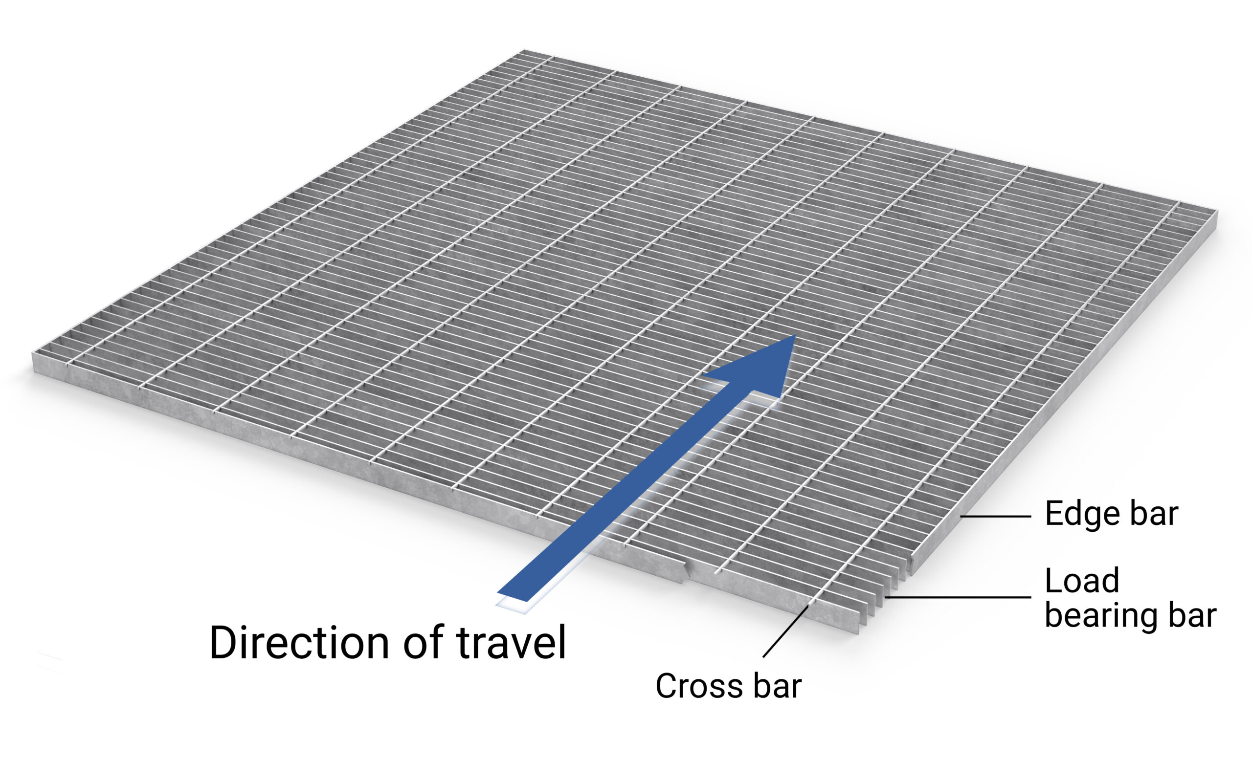
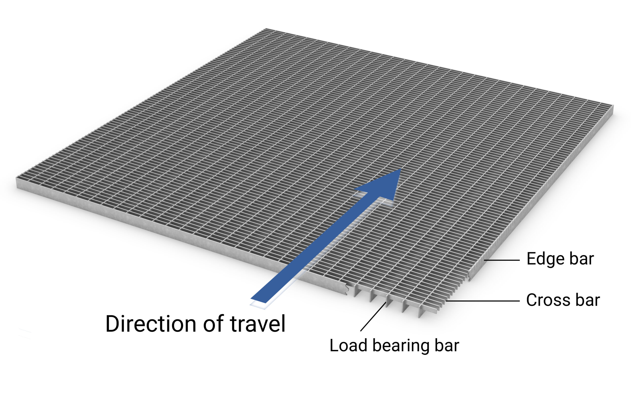
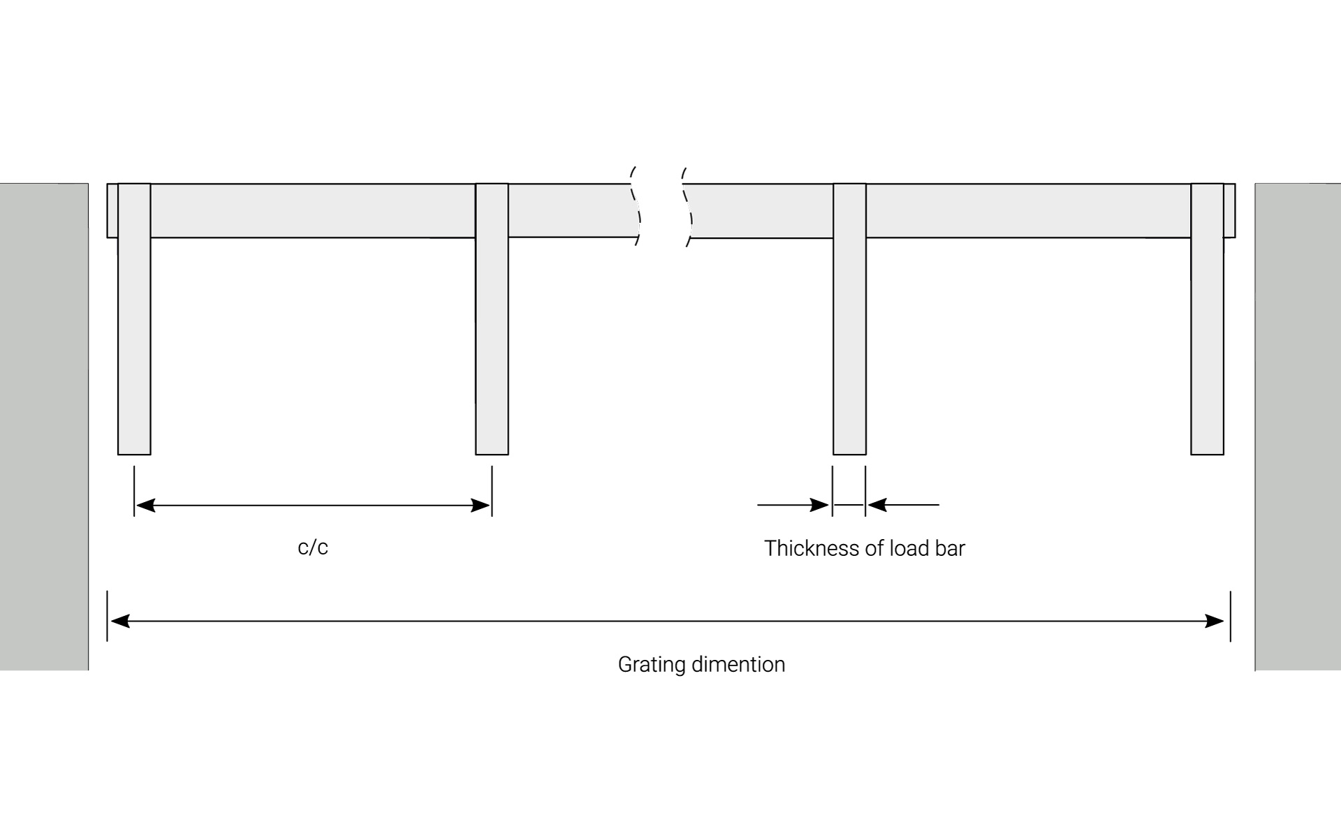
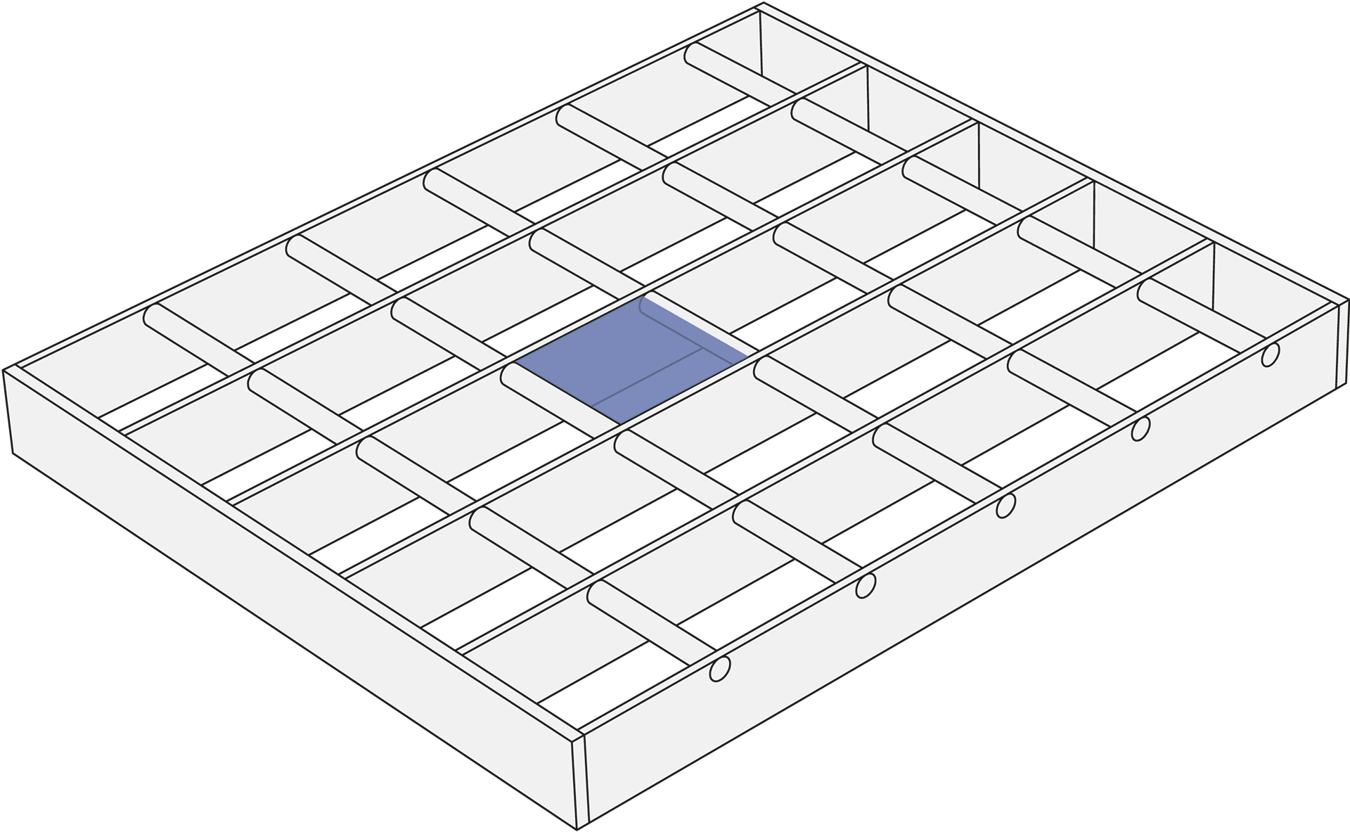
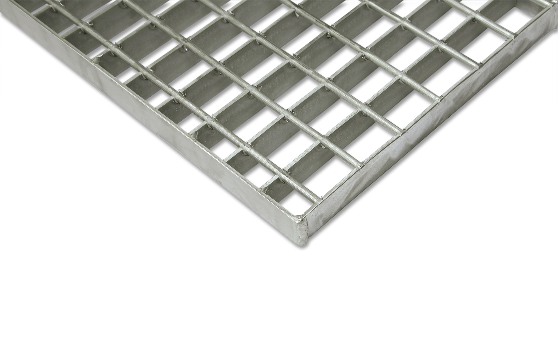
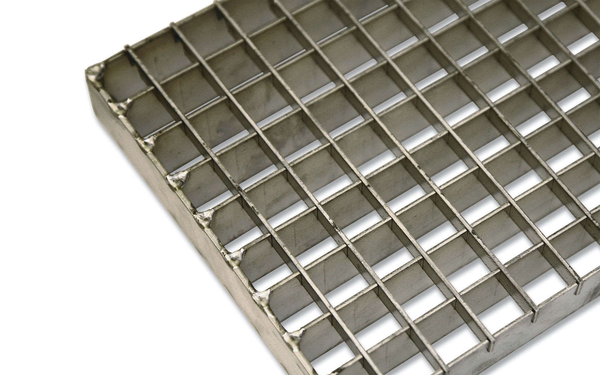
The grating’s component parts are load bearing bar, cross bar and edge bar.
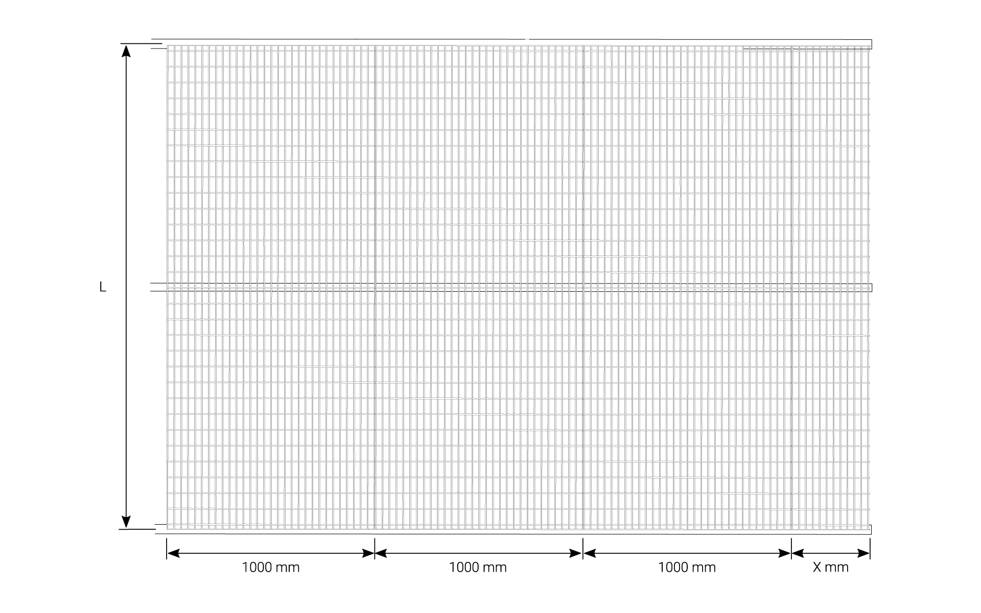
During all planning involving pressure welded grating, you should as far as possible adapt the layout to the grating’s standard width (1000 mm) to obtain the most economical alternative.
If the grating is to be laid across several supports, it is best to choose grating in larger sizes. This gives a more beautiful pattern with fewer joints.
To prevent incorrect placement of the load bearing rod (the grating’s bearing structure), avoid grating with square dimensions.
Direction of travel
Depending on which type of grating you choose for your entrance, the load bearing bars should be placed correctly.
Pressure welded grating
For pressure welded grating, the load bearing bars should be placed perpendicular to the direction of travel.
Grating type A
With entrance grating type A, the load bearing bars should be placed parallel to the direction of travel.
By placing the load bearing bars correctly, the best function for the entrance grating is achieved.
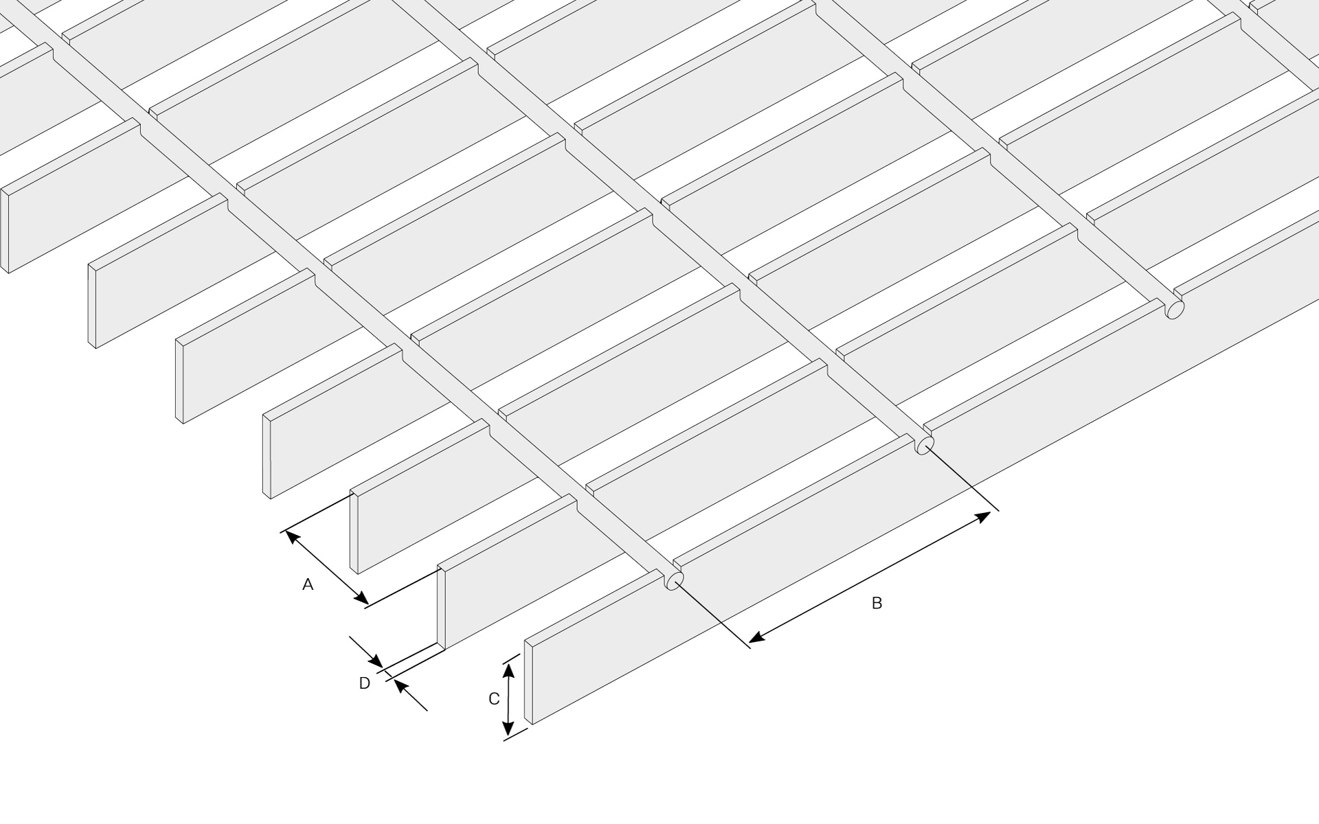
Mesh widths
We have a wide range of different mesh sizes for grating. For the mesh width, these sizes are specified c/c. The first dimension is always c/c load bearing bar and the second dimension is always c/c cross bar.
Grating with the load bearing bar height marked green below, is kept in stock for quick delivery.
| Name | Mesh width c/c AxB (mm) |
Load bearing bar thickness T (mm) | Load bearing bar heights C (mm) |
|---|---|---|---|
| B9 | 12 x 100 | 3 | 20, 25, 30, 35, 40 |
| N4 | 17 x 50 | 2 | 20, 25, 30, 35, 40 |
| N4 | 17 x 50 | 3 | 20, 25, 30, 35 |
| N6 | 17 x 75 | 2 | 20, 25, 30 |
| N9 | 17 x 100 | 3 | 20, 25, 30, 35, 40, 45, 50 |
| D4 | 22 x 50 | 3 | 20, 25, 30, 35, 40, 45, 50 |
| D4 | 22 x 50 | 4 | 30, 35, 40, 45, 50, 60 |
| D4 | 22 x 50 | 5 | 20, 25, 30, 35, 40, 45, 50, 60 |
| D6 | 22 x 75 | 2 | 25 |
| D6 | 22 x 75 | 3 | 20 |
| F4 | 25 x 50 | 3 | 20, 25, 30, 35, 40, 45, 50 |
| F4 | 25 x 50 | 4 | 30, 35, 40, 45, 50, 60, 70, 80 |
| F4 | 25 x 50 | 5 | 20, 25, 30, 35, 40, 45, 50, 60, 70, 80 |
| H3 | 34 x 37 | 2 | 20, 25, 30, 35, 40 |
| H3 | 34 x 37 | 3 | 20, 25, 30, 35, 40, 45, 50 |
| H3 | 34 x 37 | 4 | 30, 35, 40 45, 50, 60, 70, 80 |
| H3 | 34 x 37 | 5 | 20, 25, 30, 35, 40 45, 50, 60, 70, 80 |
| H4 | 34 x 50 | 2 | 20, 25, 30, 35, 40 |
| H4 | 34 x 50 | 3 | 20, 25, 30, 35, 40, 45, 50 |
| H4 | 34 x 50 | 4 | 30, 35, 40, 45, 50, 60, 70, 80 |
| H4 | 34 x 50 | 5 | 20, 25, 30, 35, 40, 45, 50, 60, 70, 80 |
| H6 | 34 x 75 | 2 | 25, 30, 40 |
| H6 | 34 x 75 | 3 | 20, 25, 30, 35, 40, 45, 50 |
| H9 | 34 x 100 | 3 | 20, 25, 30, 35, 40, 45, 50 |
| H9 | 34 x 100 | 4 | 30, 35, 40, 45, 50 |
| H9 | 34 x 100 | 5 | 20, 25, 30, 35, 40, 45, 50, 60 |
| J9 | 41 x 100 | 3 | 20, 25, 30, 35 |
| J9 | 41 x 100 | 4 | 30, 35, 40, 45, 50, 60 |
| J9 | 41 x 100 | 5 | 20, 25, 30, 35, 40, 45, 50, 60 |
| I6 | 66 x 75 | 3 | 20, 25, 30 |
| I4 | 68 x 50 | 2 | 20 |
| I9 | 100 x 100 | 3 | 20, 25, 30 |
Grating with the load bearing bar height marked green below, is kept in stock for quick delivery.
| Name | Mesh width c/c AxB (mm) |
Load bearing bar thickness T (mm) | Load bearing bar heights C (mm) |
|---|---|---|---|
| N9-T | 17 x 100 | 3 | 25, 30, 35, 40 |
| H4-T | 33 x 50 | 2 | 25 |
| H4-T | 33 x 50 | 3 | 25, 30, 35, 40, 45, 50 |
| H4-T | 33 x 50 | 4 | 30, 35, 40, 45, 50, 60, 80 |
| H4-T | 33 x 50 | 5 | 25, 30, 35, 40, 45, 50, 60 |
| F4-T | 25 x 50 | 3 | 25, 30, 35, 40, 45, 50 |
| F4-T | 25 x 50 | 4 | 30, 35, 40, 45, 50, 60 |
| F4-T | 25 x 50 | 5 | 25, 30, 35, 40, 45, 50, 60 |
| H9-T | 33 x 100 | 3 | 25, 30, 35, 40, 45, 50 |
| H9-T | 33 x 100 | 4 | 30, 35, 40, 45, 50 |
| H9-T | 33 x 100 | 5 | 25, 30, 35, 40, 45, 50, 60 |
| J9-T | 41 x 100 | 3 | 25, 30, 35, 40, 45, 50 |
| J9-T | 41 x 100 | 4 | 30, 35, 40, 45, 50, 60 |
| J9-T | 41 x 100 | 5 | 20, 25, 30, 35, 40, 45, 50, 60 |
| HN9-T | 35 x 100 | 3 | 25, 30, 35, 40, 45, 50 |
| HN9-T | 35 x 100 | 4 | 25, 30, 35, 40, 45, 50 |
| JN9-T | 41 x 100 | 3 | 25, 30, 35, 40 |
| JN9-T | 41 x 100 | 5 | 25, 30, 35, 40, 45, 50, 60 |
| Name | Mesh width c/c AxB (mm) |
Load bearing bar thickness T (mm) | Load bearing bar heights C (mm) |
|---|---|---|---|
| A22x22 | 22 x 22 | 2 | 20, 25, 30, 40, 50 |
| A33x11 | 33 x 11 | 2 | 20, 25, 30, 40, 50 |
Construction dimensions with whole mesh widths
In the table, the construction dimensions in which the grating can be obtained (with full mesh) are set out.
Marked dimensions specify standard widths.
| H also for SS. c/c 33 (mm) |
H also for SS. c/c 34 (mm) |
F c/c 25 (mm) |
D c/c 22 (mm) |
N c/c 16 (mm) |
N c/c 17 (mm) |
B c/c 12 (mm) |
I4 20/2 c/c 68 (mm) |
J c/c 41 (mm) |
JN9-T c/c 41 (mm) |
HN9-T c/c 35 (mm) |
|---|---|---|---|---|---|---|---|---|---|---|
| 1000 | 1000 | 1000 | 1000 | 1000 | 1000 | 700 | 969 | 1000 | 1000 | 1000 |
| 966 | 965 | 973 | 972 | 982 | 983 | 685 | 898 | 957 | 955 | 961 |
| 933 | 931 | 949 | 950 | 966 | 966 | 672 | 830 | 914 | 915 | 926 |
| 900 | 897 | 923 | 928 | >949 | 949 | 659 | 761 | 872 | 874 | 890 |
| 867 | 862 | 898 | 906 | 933 | 931 | 646 | 692 | 830 | 832 | 855 |
| 834 | 828 | 873 | 884 | 916 | 914 | 633 | 624 | 788 | 791 | 820 |
| 801 | 794 | 849 | 862 | 900 | 897 | 620 | 554 | 745 | 750 | 785 |
| 768 | 760 | 825 | 840 | 883 | 880 | 608 | 487 | 700 | 709 | 750 |
| 734 | 725 | 799 | 818 | 867 | 863 | 596 | 420 | 662 | 668 | 714 |
| 700 | 691 | 774 | 797 | 850 | 846 | 584 | 350 | 621 | 626 | 679 |
| 668 | 657 | 750 | 775 | 834 | 829 | 571 | 282 | 580 | 585 | 644 |
| 635 | 623 | 725 | 753 | 817 | 811 | 559 | 213 | 540 | 544 | 608 |
| 602 | 588 | 700 | 731 | 801 | 794 | 547 | 143 | 500 | 503 | 573 |
| 568 | 554 | 674 | 709 | 784 | 777 | 535 | 75 | 456 | 462 | 538 |
| 534 | 520 | 650 | 687 | 768 | 760 | 522 | 416 | 421 | 503 | |
| 500 | 486 | 625 | 665 | 751 | 743 | 511 | 375 | 380 | 467 | |
| 469 | 451 | 600 | 643 | 734 | 726 | 500 | 334 | 338 | 432 | |
| 436 | 417 | 575 | 621 | 718 | 709 | 485 | 293 | 297 | 397 | |
| 403 | 383 | 550 | 599 | 700 | 691 | 473 | 252 | 256 | 362 | |
| 370 | 348 | 526 | 577 | 683 | 674 | 460 | 211 | 215 | 326 | |
| 337 | 314 | 500 | 555 | 665 | 657 | 448 | 171 | 174 | 291 | |
| 304 | 280 | 475 | 533 | 649 | 640 | 436 | 130 | 132 | 256 | |
| 271 | 246 | 451 | 511 | 632 | 623 | 424 | 89 | 91 | 221 | |
| 238 | 211 | 426 | 490 | 616 | 606 | 411 | 48 | 50 | 185 | |
| 205 | 177 | 401 | 468 | 600 | 589 | 399 | 150 | |||
| 171 | 143 | 377 | 446 | 583 | 571 | 387 | 115 | |||
| 139 | 109 | 352 | 424 | 568 | 554 | 374 | 80 | |||
| 106 | 74 | 327 | 402 | 550 | 537 | 362 | 44 | |||
| 73 | 40 | 302 | 380 | 534 | 520 | 350 | ||||
| 40 | 278 | 358 | 518 | 503 | 338 | |||||
| 253 | 336 | 500 | 486 | 326 | ||||||
| 228 | 314 | 483 | 469 | 313 | ||||||
| 204 | 292 | 465 | 452 | 301 | ||||||
| 179 | 270 | 449 | 434 | 289 | ||||||
| 154 | 248 | 433 | 417 | 276 | ||||||
| 130 | 226 | 416 | 400 | 264 | ||||||
| 105 | 204 | 400 | 383 | 252 | ||||||
| 81 | 182 | 383 | 366 | 240 | ||||||
| 56 | 160 | 367 | 349 | 228 | ||||||
| 32 | 139 | 351 | 332 | 215 | ||||||
| 117 | 334 | 314 | 203 | |||||||
| 95 | 318 | 297 | 191 | |||||||
| 73 | 302 | 280 | 178 | |||||||
| 51 | 285 | 263 | 166 | |||||||
| 29 | 269 | 246 | 154 | |||||||
| 252 | 229 | 142 | ||||||||
| 236 | 212 | 130 | ||||||||
| 220 | 194 | 117 | ||||||||
| 203 | 177 | 105 | ||||||||
| 187 | 160 | 93 | ||||||||
| 171 | 143 | 80 | ||||||||
| 154 | 126 | 68 | ||||||||
| 137 | 109 | 56 | ||||||||
| 122 | 92 | 44 | ||||||||
| 105 | 74 | 31 | ||||||||
| 89 | 57 | 19 | ||||||||
| 72 | 40 | |||||||||
| 56 | 23 | |||||||||
| 40 | ||||||||||
Opening area
By opening area, we mean the free dimension in the grating. A piece of information that often comes up in discussions about the transmission of light.
| Name | Mesh width | Load bearing steel dim. | Cross bar steel dim. | Opening area % |
|---|---|---|---|---|
| B9 | 12 x 100 | 3 | 6.5 | 68.9 |
| N4 | 17 x 50 | 2 | 5 | 77.8 |
| N4 | 17 x 50 | 3 | 6.5 | 68.7 |
| N6 | 17 x 75 | 2 | 4 | 82.6 |
| N9 | 17 x 100 | 3 | 5 | 77.3 |
| D4 | 22 x 50 | 3 | 6.5 | 73.2 |
| D4 | 22 x 50 | 4 | 6.5 | 68.6 |
| D4 | 22 x 50 | 5 | 6.5 | 64.0 |
| F4 | 25 x 50 | 3 | 6.5 | 74.7 |
| F4 | 25 x 50 | 4 | 6.5 | 70.6 |
| F4 | 25 x 50 | 5 | 6.5 | 66.5 |
| H3 | 34 x 37 | 2 | 4 | 83.2 |
| H3 | 34 x 37 | 3 | 4 | 80.2 |
| H3 | 33 x 37 | 4 | 6.5 | 70.1 |
| H3 | 33 x 37 | 5 | 6.5 | 67.0 |
| H4 | 34 x 50 | 2 | 5 | 83.8 |
| H4 |
33 x 50 |
3 | 5 | 80.7 |
| H4 | 33 x 50 | 4 | 6.5 | 74.6 |
| H4 | 33 x 50 | 5 | 6.5 | 71.5 |
| H6 | 34 x 75 | 2 | 4 | 88.4 |
| H6 | 34 x 75 | 3 | 5 | 83.7 |
| H9 | 33 x 100 | 3 | 6.5 | 84.2 |
| H9 | 33 x 100 | 4 | 6.5 | 81.1 |
| H9 | 33 x 100 | 5 | 6.5 | 78.0 |
| J9 | 41 x 100 | 3 | 6.5 | 86.0 |
| J9 | 41 x 100 | 4 | 6.5 | 83.5 |
| J9 | 41 x 100 | 5 | 6.5 | 81.0 |
| I6 | 66 x 75 | 3 | 5 | 88.2 |
| I9 | 100 x 100 | 3 | 6.5 | 90.2 |
| Name | Mesh width | Load bearing steel dim. | Cross bar steel dim. | Opening area % |
|---|---|---|---|---|
| N9-T | 16 x 100 | 3 | 5 | 77.3 |
| H4-T | 33 x 50 | 2 | 5 | 83.8 |
| H4-T | 33 x 50 | 3 | 5 | 80.7 |
| H4-T | 33 x 50 | 4 | 6.5 | 74.6 |
| H4-T | 33 x 50 | 5 | 6.5 | 71.5 |
| F4-T | 25 x 50 | 3 | 6.5 | 74.7 |
| F4-T | 25 x 50 | 4 | 6.5 | 70.6 |
| F4-T | 25 x 50 | 5 | 6.5 | 66.5 |
| H9-T | 33 x 100 | 3 | 6.5 | 84.2 |
| H9-T | 33 x 100 | 4 | 6.5 | 81.1 |
| H9-T | 33 x 100 | 5 | 6.5 | 78.0 |
| J9-T | 41 x 100 | 3 | 6.5 | 86.0 |
| J9-T | 41 x 100 | 4 | 6.5 | 83.5 |
| J9-T | 41 x 100 | 5 | 6.5 | 81.0 |
| HN9-T | 35 x 100 | 3 | 6.5 | 70.8 |
| HN9-T | 35 x 100 | 5 | 6.5 | 65.0 |
| JN9-T | 41 x 100 | 3 | 6.5 | 69.2 |
| JN9-T | 41 x 100 | 5 | 6.5 | 64.2 |
| Name | Mesh width | Load bearing steel dim. | Cross bar steel dim. | Opening area % |
|---|---|---|---|---|
| A22x22 | 22 x 22 | 2 | 2 | 82.0 |
| A33x11 | 33 x 11 | 2 | 2 | 76.0 |
Tolerances and Dimensions
Length & width dimensions
Our production is based on fixed tolerances for the length, width and diagonal dimensions. The tolerance is set to +0 / -4 mm.
Max. length of cross bar ends
Cross bar ends have a maximum protrusion of 2 mm.
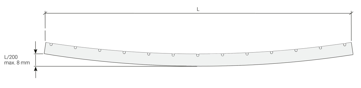
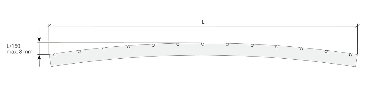
Load bearing bar deflection
Maximum load bearing bar deflection is based on type.
For convex load bearing bar deflection, use span length through 150 (L/150) and a maximum of 8 mm.
For concave load bearing bar deflection, use span length through 200 (L/200) and a maximum of 8 mm.
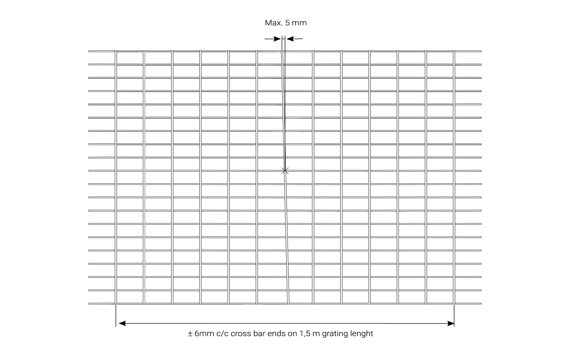
Cross bar division
Our production is based on fixed tolerance for the cross bar division. The placing of the cross bars follows the specified mesh width with tolerances according to the diagram.
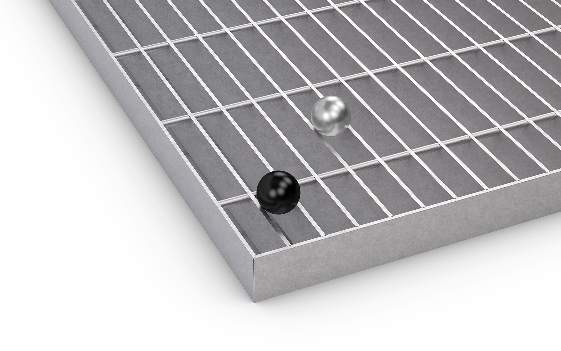
Ball proof requirements
In instances where the EU Safety of machinery 14122-2 applies to your environment, the choice of grating used must be preceded by a risk assessment.
In these instances , the following requirements apply:
- The opening width of the grating used on work platforms or gangways must be narrow enough to prevent a 35 mm in diameter ball from passing through.
- Grating that runs above a work site must, in contrast to temporary passageways, have openings that do not allow a ball measuring 20 mm in diameter to pass through.
20 mm
In order to satisfy the 20 mm ball proof requirement, we offer a plethora of different fine mesh grating models. The most popular grating model compliant with the 20 mm ball proof requirement is N6. However, B9, N6, N9, D4, D6, HN9-T, A22x22, and A33x11 variants are also follow in agreement.
35 mm
All our grating types, except for our large mesh gratings, are compliant with the 35 mm ball proof requirement. Out of these, the most popular and cost-effective options are the H3 and H6. In addition, 35 mm wide balls do not pass through grating with the following mesh widths – B9, N4, N6, N9, D4, D6, F4, H3, H6, H9, HN9-T, A22x22, and A33x11.
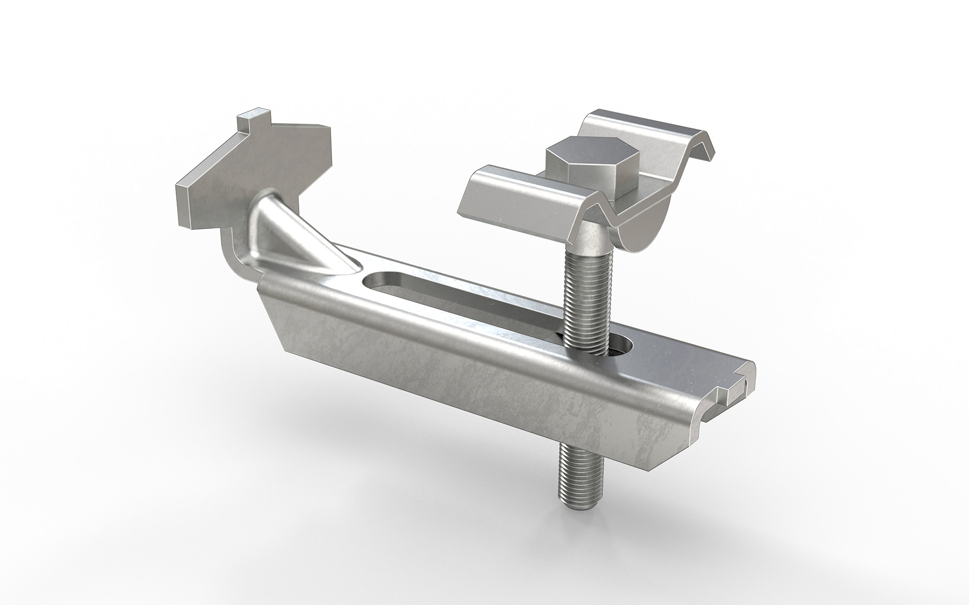
Fixing
For fixing gratings, we off a number of different fixings. Both complete clamps consisting of top section, bottom section, bolt and nut or, alternatively, top section and fixing screw. For gratings trafficked by heavy vehicles, we also offer mounting lugs welded to the bottom of the grating’s mesh.
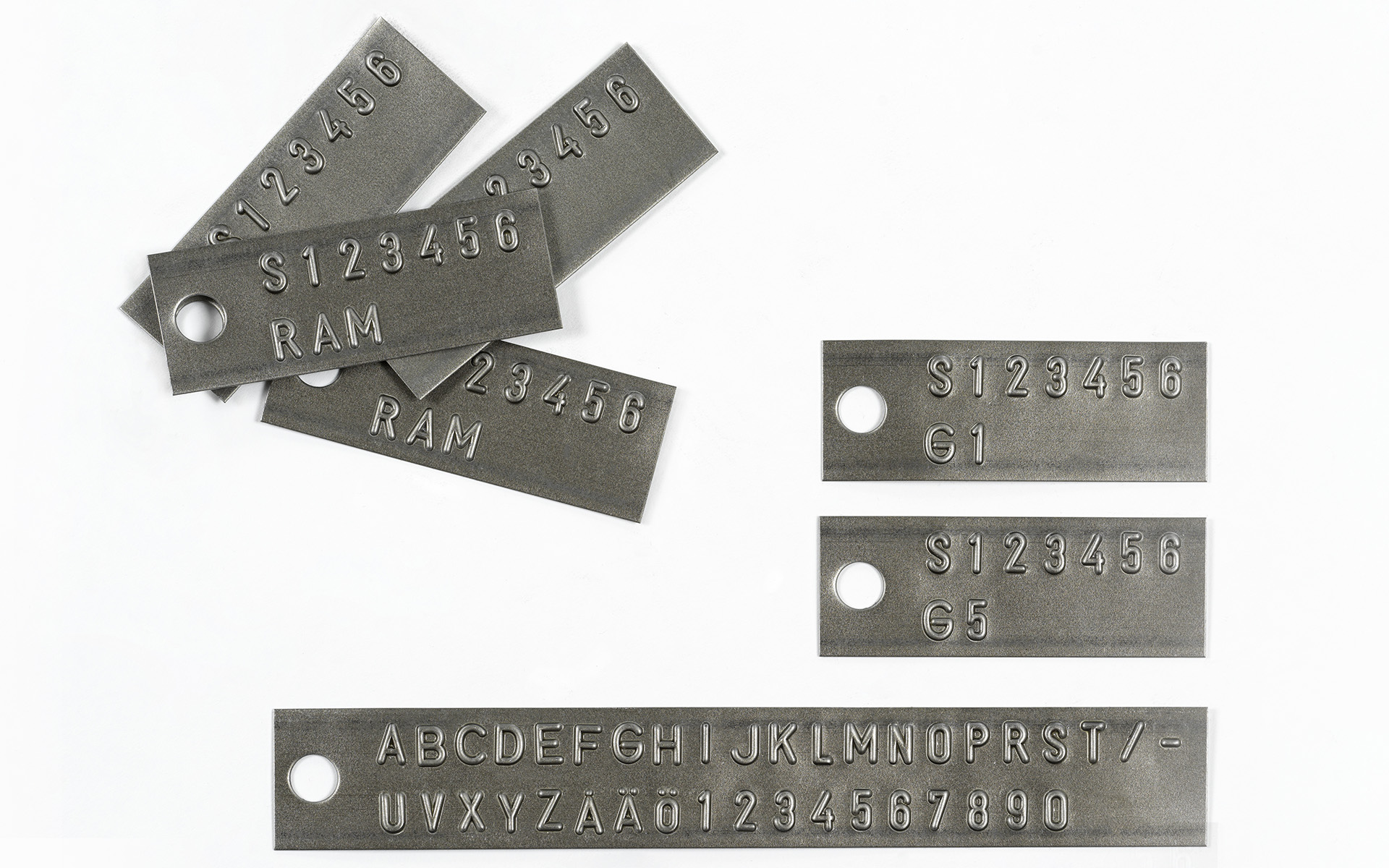
Marking
Each grating can be provided with a substantial identification tab with clear characters that refer to the layout drawing, which makes the assembly work easier. Frequently used for slightly larger projects.
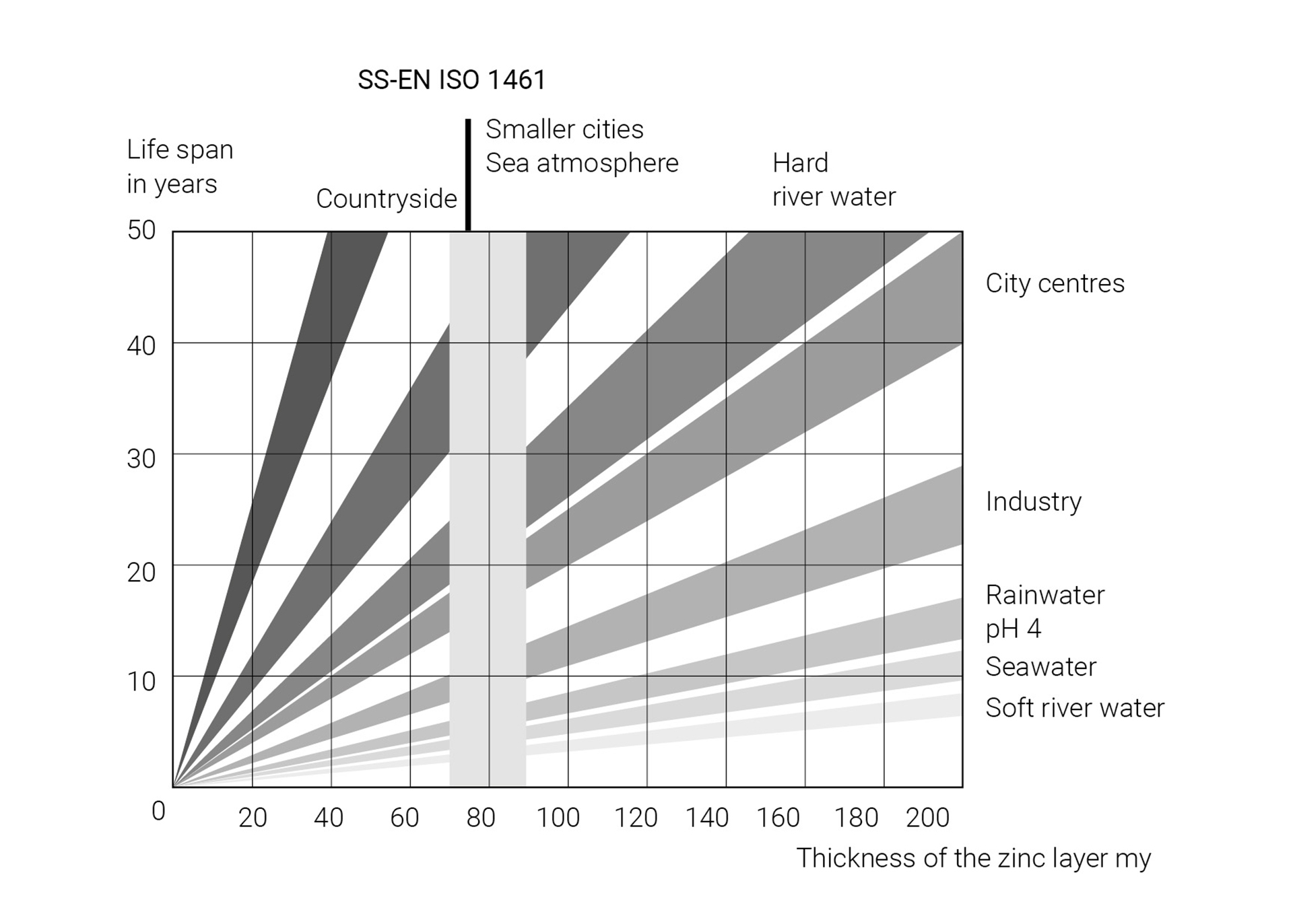
Surface treatment
Hot dip galvanisation
The diagram shows the average service life for different thicknesses of zinc in different environments.
Treatment of stainless steel
Stainless steel grating is pickled in order to restore the material after welding.
Treatment of aluminium
Aluminium grating is pickled to attain a good surface finish.
Film Z-profile kerb angle frames assembly
Load tables
In our load tables, you will find conditions for all our grating types and a number of different load cases.
Calculations are made according to Eurocode. Specified pressure surfaces and loads are specified.
Our load tables can be found below, under Documentation.
Weights grating
For information on weights for our gratings for pedestrian traffic, vehicle traffic and full-size gratings, see documentation below.